G-code for furniture CNC: from drawing to machine
Updated: CNC5 min readBy moducut team
Summarize this article with an AI tool:
Short answer
What is G-code?
G-code is the common language of CNC machines. Each line is a command: a rapid move, a cutting move, starting the spindle, changing tools and so on. Common commands are:
- G0. Rapid positioning without cutting.
- G1. Cutting in a straight line at a set feed rate.
- G2 and G3. Cutting along an arc, clockwise and counterclockwise; for corner radii and circles.
- M3 and M5. Starting and stopping the spindle.
- M6. Tool change (on machines with a tool changer).
- F and S. Feed rate and spindle speed.
In furniture work you do not write these commands by hand; the software generates the G-code from the shape of the parts, the holes and the grooves. Still, knowing the basic commands makes it easier to read the program and find the problem when the machine makes an unexpected move. For a short definition, see the G-code entry.
The workflow from drawing to G-code
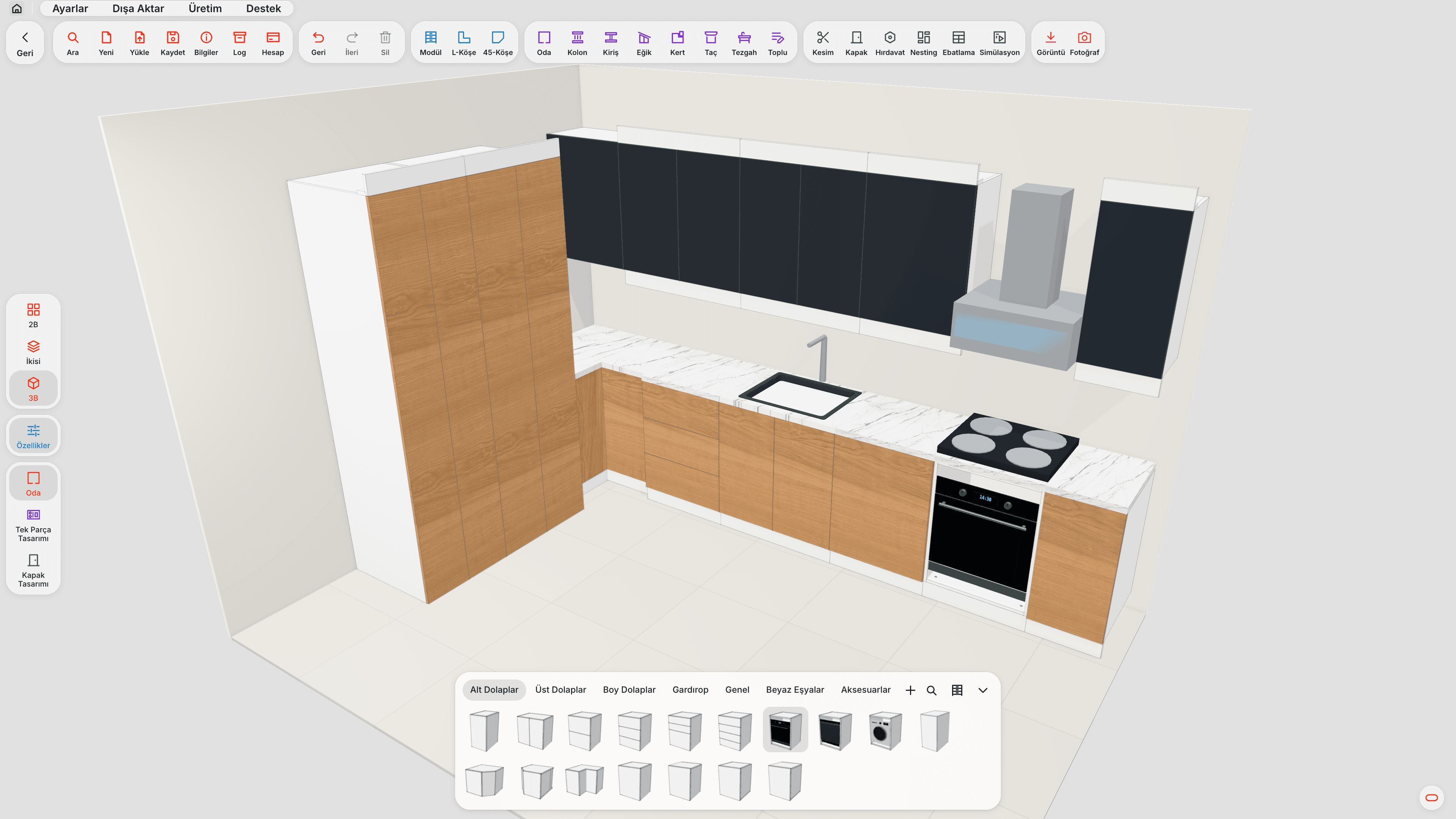
- Drawing. Cabinets are designed for the room; parts, holes and grooves come from the drawing.
- Cut list. The size, quantity and material of the parts are produced.
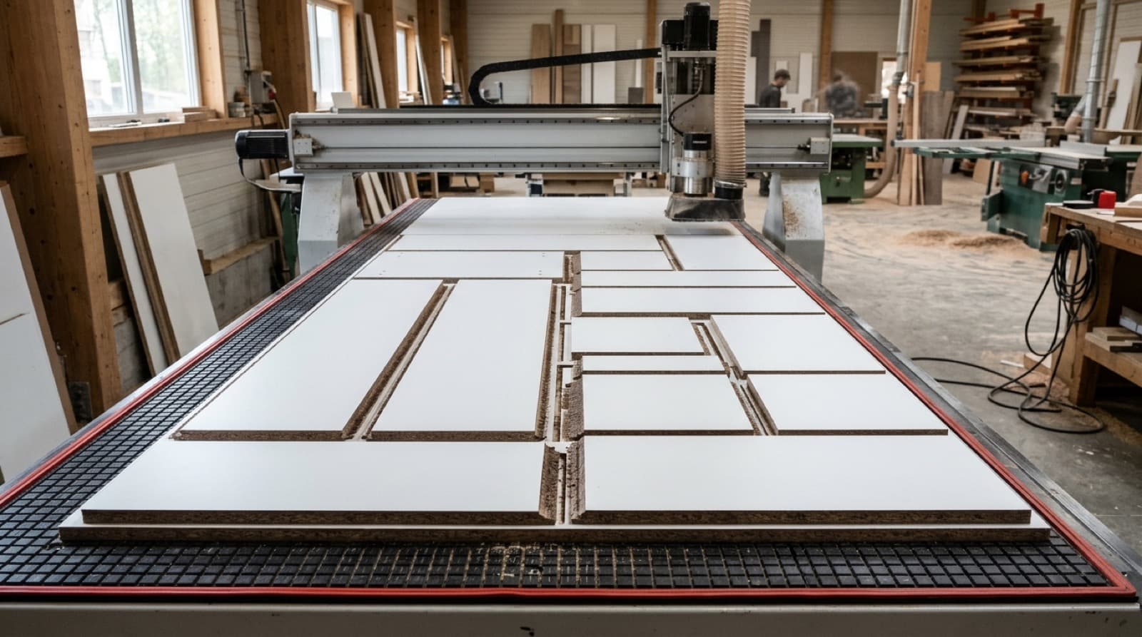
- Nesting. Parts are placed on the sheets; an allowance equal to the bit diameter is left between them.
- Tool and operation selection. You decide which bit to use for contour, groove and drilling operations.
- Simulation. The program is watched step by step on screen before it goes to the machine.
- G-code output. A file the machine will read is written for each sheet and transferred to the machine.
- Labeling. Cut parts are labeled, so it is clear where each part goes at assembly.
Why does the post processor matter?
Although G-code is a standard, not every controller reads it the same way. Some controllers expect line numbers (N10, N20…), some mark comment lines differently; tool change and program start/end commands also vary from controller to controller. On some controllers, even a comment line with non-ASCII characters (such as Turkish letters) can stop the program.
The layer that formats the program for the machine is called the post processor. Find out from your machine manufacturer or the controller manual which format your machine expects (such as GRBL, Mach3, LinuxCNC or an ISO-based controller). Some machines read their own file format instead of G-code; for example, Biesse machining centers expect CIX programs. If you use a separate CAM program, parts can also be exported as DXF. For these formats, see the CIX and DXF entries.
Preparation checklist before moving to CNC
- Tools. Decide which bit diameters you will work with; contour, groove and drilling may need separate tools.
- Table and hold-down. On a vacuum table, the spoilboard must be flat and clean so small parts do not slip.
- Zero point. Make sure the machine's X, Y and Z zero is at the same corner as the zero in the program.
- Board thickness. Measure the real board thickness; the cutting depth is set from it plus the allowance for cutting into the spoilboard.
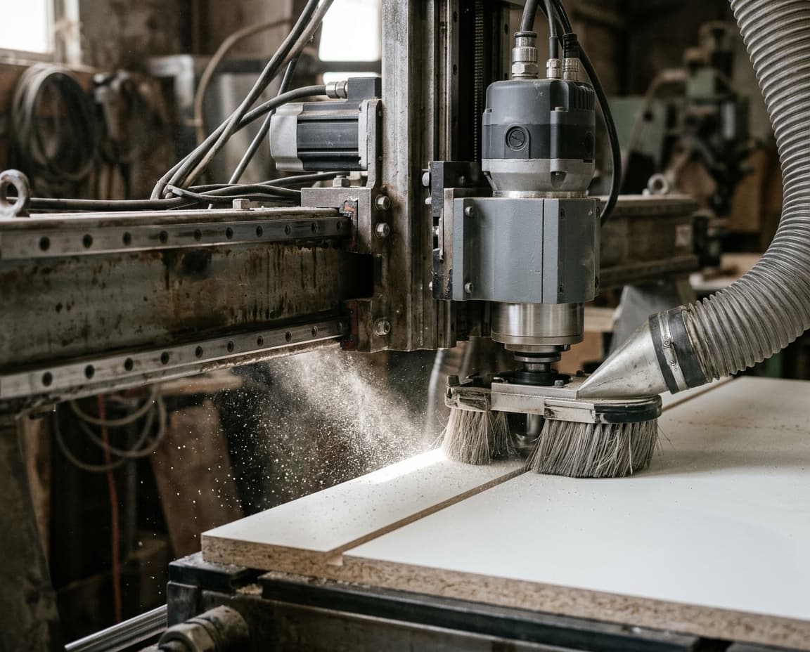
- Dust extraction. MDF and particleboard dust is a problem for both health and the machine; do not start cutting without extraction running.
Cutting order and small parts
In common practice, holes and grooves are cut first and the part contour last. Once the contour is cut, the part is free from the sheet; a hole or groove cut after that point can land in the wrong place on a part that has shifted.
Small parts struggle to stay put on the vacuum. For this, the contour can be cut in two passes: the first pass cuts through most of the board, the last pass removes the remaining thin skin. That way parts stay attached to the sheet until the last moment. Cutting small parts first and large parts later also helps hold-down.
Common mistakes in the first programs
- Wrong tool diameter. If the bit diameter in the program differs from the bit fitted, parts come out too small or too big.
- Wrong Z depth. A depth written without measuring the board thickness either does not cut the part through or goes too deep into the table.
- Two-sided operations. If a part has holes or grooves on both faces, the part must be flipped and a separate program run for the second face.
- Old program. If connector or size settings changed after nesting, the holes in the old program no longer match the new drawing.
- Production run without a test. With a new post or a new construction method, check the first sheet, if possible by running it in the air without the tool touching the board.
G-code in moducut
In moducut, machines and tools are defined in Settings › CNC Settings. You can choose from preset profiles or define your own machine with Add New; header, tool change and end lines, the comment marker, line number step, file extension (such as .tap, .nc, .gcode), safe Z and table sizes are set for the machine. Bit diameter and cutting speeds are entered per tool; contours and holes are recalculated from the diameter you enter.
Sheets are prepared with Production › Nesting. In Nesting Results, “Save All G-Code” or “Send This Sheet to Production” opens the Create CNC Production File window: here you choose the machine, set the tool for each operation, and choose single-pass or pocketing for grooves. Contour cutting is two passes by default; the thickness of the last pass can be set, or single pass chosen if you prefer. The simulation shows the program step by step before you send it to the machine. Files are written sheet by sheet into a folder named after the project, with each output in its own date-time folder.
For parts with operations on both faces, a flip-side program is saved separately; sheets can also be exported as DXF, and with the Biesse profile the sheet program is written as CIX. If a setting that affects holes changed after nesting, or the holes on the sheet do not match the current 3D model, you get a warning before the G-code is produced. See the G-code and CNC page for details.
Frequently asked questions
Do I need a separate CAM program for furniture CNC?
Not necessarily. With software that writes G-code directly from the drawing, the CAM step can be skipped; if you prefer to work with a separate CAM program, you can export the parts as DXF.
Does G-code work the same on every CNC machine?
No. Although the basic commands are shared, details such as program start, tool change, comments and line numbers vary by controller. The program should be prepared with a post setting that suits your machine and tested on the first sheet.
Does moducut run on a Mac?
No, moducut runs on Windows computers. See the download page for installation.