Skip to content
NewsNew: Door and Entry Door design screens are complete

What’s new

Everything that comes to moducut, in date order. Updates are included in your license.

WindowsVersion 0.4.247

Updates to Reksis T6 Shelf Pin Drilling Operations

Reksis T6 shelf pin drilling operations and saved tool list exports have been updated.

  • When a 4.5 mm drill bit is used for the Reksis T6 shelf pin, moducut now accurately drills only Ø4.5 holes.

  • Separate projects are not combined into one cutting plan.
Try it freeFor Windows · in both plans
WindowsVersion 0.4.246

Updated Tooling for Cabineo and Hinge Cup Machining

Fixed an issue where the Cabineo drill bit was incorrectly used to pocket hinge cups laterally. Cabineo bits now only perform drilling, while hinge cup pocketing is routed to the proper routing tool.

  • Updated CNC tool assignments for Cabineo drilling and hinge cup pocketing operations.

  • Prevented the Cabineo drill bit from attempting side-cutting on hinge cups, assigning the pocketing operation to the router bit instead.

  • Separate projects are not combined into one cutting plan.
Try it freeFor Windows · in both plans
WindowsVersion 0.4.245

Updated Cushion Settings for Reksis Machines

Default cushion thickness for Reksis CNC machines has been updated to 13.1 mm. Explanations and guidance have been clarified for machines with Z-zero below the cushion.

  • Updated default cushion thickness preset to 13.1 mm for Reksis CNC machines.

  • Clarified cushion explanations for machines where Z-zero is set below the cushion.

  • Separate projects are not combined into one cutting plan.
Try it freeFor Windows · in both plans
WindowsVersion 0.4.244

Selecting and Editing Drawings Across Multiple Parts

You can now select and edit drawings across different parts simultaneously using the selection box. All selected drawings can be moved, copied, rotated, or deleted together in a single step.

  • Added the ability to select drawings across multiple parts at once using the selection frame.

  • Drawings selected from different parts can now be moved, copied, rotated, scaled, mirrored, and deleted together around a shared center.

  • Separate projects are not combined into one cutting plan.
Try it freeFor Windows · in both plans
WindowsVersion 0.4.243

Hole Alignment Updated for Blum Lift Mechanisms

Side panel hole positions for Blum HK top, HS, HL, and HF lift systems have been updated. Holes are now measured from the underside of the top panel according to technical specifications.

  • Side panel hole positioning for Blum HK top, HS, HL, and HF mechanisms is now calculated from the bottom of the top panel.

  • Separate projects are not combined into one cutting plan.
Try it freeFor Windows · in both plans
WindowsVersion 0.4.242

Simplified Butterfly Connectors and Hole Placement Fixes

Butterfly connectors are now consolidated into a single option in the menu. Hole positions have been refined to prevent assembly issues and panel damage.

  • Butterfly connector is now available as a single selection, automatically placing male holes on the touching panel and female holes on the mating panel.

  • Butterfly connectors in existing projects automatically update to the new format when opened.

  • Female holes for butterfly connectors moved to the inner side of the corner to keep them from being covered by the panel.
  • Removed the center marking hole to prevent screws from penetrating the panel.

  • Separate projects are not combined into one cutting plan.
Try it freeFor Windows · in both plans
WindowsVersion 0.4.241

Advanced Tool Selection and Optimized Cutting Paths

This release introduces the ability to assign specific tools to operations. Additionally, joint and groove cutting paths have been optimized, and simulation timings are now more accurate.

  • Added the ability to assign specific tools using 'Automatic' or 'Selected tools' options, with system warnings for incompatible tool selections.

  • Updated joint and groove cutting to a zigzag toolpath, eliminating unnecessary rapid moves and completing one door before moving to the next.
  • Updated simulation time calculations and tool change movements according to machine settings.

  • Fixed tool list errors and incorrect tool assignments in door operations.

  • Separate projects are not combined into one cutting plan.
Try it freeFor Windows · in both plans
WindowsVersion 0.4.240

Simplified CNC Tool Settings

Tool position parameters have been removed from CNC settings, assuming all listed tools are available on the machine. Additionally, a visual tool magazine has been added to the simulation.

  • Tools in the simulation are now visually displayed in a representative 20-slot tool magazine.

  • Removed tool position parameters from CNC settings; all listed tools are now automatically considered available on the machine.

  • Separate projects are not combined into one cutting plan.
Try it freeFor Windows · in both plans
WindowsVersion 0.4.239

Automatic Horizontal View in Simulation and Nesting

Vertical boards and sheets now automatically display with their long edge horizontal when opening simulation and nesting screens. You can still manually rotate the view using the controls.

  • Vertical boards and sheets in simulation and nesting views now open horizontally by default.

  • Separate projects are not combined into one cutting plan.
Try it freeFor Windows · in both plans
WindowsVersion 0.4.235

Automatic Language Selection on Initial Setup

During setup and first launch, moducut now automatically matches its language with your website preference.

  • Installation and first launch language is automatically set according to the website language preference.

  • Separate projects are not combined into one cutting plan.
Try it freeFor Windows · in both plans
WindowsVersion 0.4.234

Panel and Reverse Operation Images Added to G-Code Output

Images showing panel details and reverse side operations are now included with G-code outputs. This makes it easier to verify parts and double-sided machining at the CNC machine.

  • Visual images of panels and reverse side operations are automatically generated alongside G-code exports.

  • Separate projects are not combined into one cutting plan.
Try it freeFor Windows · in both plans
WindowsVersion 0.4.231

CNC Machine Selection Updated

The CNC machine selection list has been updated to temporarily offer only the moducut option.

  • The CNC machine selector currently includes only the moducut option.

  • Separate projects are not combined into one cutting plan.
Try it freeFor Windows · in both plans
WindowsVersion 0.4.3

moducut 0.4.3

In-app video tutorials, a single notch where a column meets a beam, more accurate production for gola profiles and top rails, a door model library and more efficient nesting.

Video tutorials inside the app

The Tutorials page on the start screen now has 10 narrated videos: new project, adding modules, room layout, wardrobes and legs, custom module design, beam notching, bulk changes, nesting and G-code, production lists and CNC simulation. The wardrobe and CNC simulation tutorials are new.

Tutorial series

Columns, beams and notches

  • Where a column and a beam notch intersect, they are closed off as a single gap; the column upright stays in one piece and the beam area is routed out.
  • Connectors that fall in the routed area move to the remaining solid section.
  • An overlay back panel covers 18 mm of the notch piece under the beam; grooved and rebated back panels enter that piece through a groove.
  • Connectors on notch pieces are set to outside or inside under General Settings › Notch › Connectors (outside by default).
  • In 3D the grooves of notch pieces are drawn; grooves opened on a face are actually cut.
  • The Notch button now has its own icon.

Accurate cutting on gola profiles

  • The J gola profile runs uninterrupted along the module; the upright is always notched at the J line.
  • The C gola profile passes through the upright’s recess and ends on its opposite face.
  • With “No carcass groove” selected, the upright is not routed only for C; for J it is still notched.
  • With a J gola, the vertical front rail above a door is removed; the horizontal rail above a drawer stays.

Top rails and uprights

  • The upright extends by the top panel thickness; rails are notched into the upright.
  • The vertical front rail is split in two: horizontal above drawers and vertical above doors; split rails end on the face of the upright.

Door and front gaps

  • Right-click › Door Model opens the door library.
  • Patterned doors are drawn in the room with the finished door relief.
  • The gap of fronts at the carcass edge becomes 0. If there is a module next to it, the gap between the two fronts is automatically shared half and half.
  • Zero values are also shown in the door gap dimension; entering a value on the label changes that carcass’s edge gap.
  • The old 1.5 mm top, bottom and side gaps on drawer fronts become 0. Existing settings are updated automatically.
  • Doors and drawer fronts touching a side end panel extended to the door face are pulled back by the gap between two doors; double doors are equalized.
  • When a module is copied, handles fitted to individual doors and per-part rails are copied too.

Nesting

  • Parts that spill onto the next sheet are placed back into the empty space on the previous sheet, so fewer sheets are used.
  • The final pass of an inner cut is made right after its own part’s sizing cut.

Interface

  • Ribbon groups are now colored: File burgundy, Edit orange, Room Design purple, Production brand green.
  • The selection highlight is light orange.
  • Job Tracking now starts with a “New job” button and a job name field.
Try it freeFor Windows · in both plans
WindowsVersion 3.0.3

Door Design is here

You can now design doors inside moducut and send them to the CNC as an order. Curved cabinet edges, job tracking and grain matching also arrive in this release.

Door Design

Opens with the Room · Single Part · Door Design switch on the right of the bottom bar. Doors sit row by row in an order list; the preview shows 2D toolpaths or a 3D relief.

  • New door, step by step: Size, Sloped, Arched, Glass, Handle, Height, Drawer.
  • Door Library: Door, Entry Door and Divider models, the moducut collection that ships with the program (MC001…) and your own patterns (My Patterns).
  • Parametric Pattern: frames, pockets, center panel, border, motif and edge profile; kept with Save to Library.
  • Import from project: doors and drawer fronts of the cabinets in the project come into the order.
  • Order: customer, project and phone; total m², material, hardware, machining time and grand total. Import from Excel, export to Excel, CSV and Print.
  • Doors enter the existing production line through Nesting, Cut list and Labels.
  • Library patterns can also be used on cabinet doors (Part Properties › Door model) and in Single Part (Door button); in the room they appear as a 3D relief.

Curved cabinet

You can make the left or right front corner of a cabinet curved. The setting is under Module Options › Carcass › Curved Edge: turn on the corner and enter the radius and the straight section.

The curved side is cut as a single piece; kerf grooves are cut into its inner face along the curve. Shelves and the countertop get a matching radius at the same corner. If you pick the kerfing cutter from the tool library, the number and spacing of kerfs are set automatically for that cutter.

  • Connectors are placed outside the curve, on the straight section, and kept away from the gola profile, shelf pins, runners and hinges.
  • Adjacent doors are equal; front gaps come from General Settings.
  • A warning about the required V-groove cutter appears in Nesting Results.

Module editing

  • Mirror Copy in the right-click menu creates a copy with the interior layout mirrored left to right.
  • Right-click › Properties opens the properties of the clicked part; Cabinet Properties are in a floating panel on the right.
  • With multiple sections selected, shelves, horizontal dividers, uprights, drawers and hanging rails are added to every selected compartment.
  • Drawer front, drawer box and box thickness are chosen separately under Module Options › Material; the box grain direction is separate for the sides, front and back.
  • Bulk Change › Door sets the sheet grain direction for doors and drawer fronts.
  • Choices in the Handle section are previewed: Apply keeps them, Cancel reverts.
  • Job Tracking: project price, payments, expenses, delivery date and appointments; monthly summary and shop expenses. Job Tracking on the start screen, File › Account in the editor.
  • Grain matching in Nesting: on patterned sheets, doors and drawer fronts in the same column are cut one after another.
  • Inner cuts (glass cut-outs, through drawings) are set separately from sizing: With or Without contour, first and last pass.
  • General Settings › Consumables and Cost: consumable and labor prices that apply to all projects.
  • Section back panel, framed glass door and glass color, handle color and new handle models, routed handle on the door.
  • Drawer runners and lift mechanisms in 3D; Hide Drawer Boxes on the bottom bar.
  • Appliances group in the library and 3D images of modules; Upload texture for your own decor.

  • Door and drawer front gaps default to 2.5 mm top and sides, 0 at the bottom. Values you enter manually are kept.
  • The glass rebate is machined in fewer passes.
  • Drawer Runner and Handle records appear as cards in General Settings.
  • Draw Module step by step: Dimensions › Material › Carcass › Draw Module; a new module starts with 18 mm board.
  • Remove This Sheet from Production / Undo in Nesting Results.
  • Single-line option in the Text tool and a live preview of the font.
  • Separate colors for ribbon groups, new icons.

  • Curved edges only on front corners (left / right).
  • In the room, all doors of a carcass get the same door pattern.
  • Separate projects are not combined into one cutting plan.
  • In the trial version, a total of 10 sheets can be sent to production.
Try it freeFor Windows · in both plans
Windows

October 2026 update

This update brings two big changes: the sizing area has arrived, and export to CNC is now available to everyone.

Sizing area

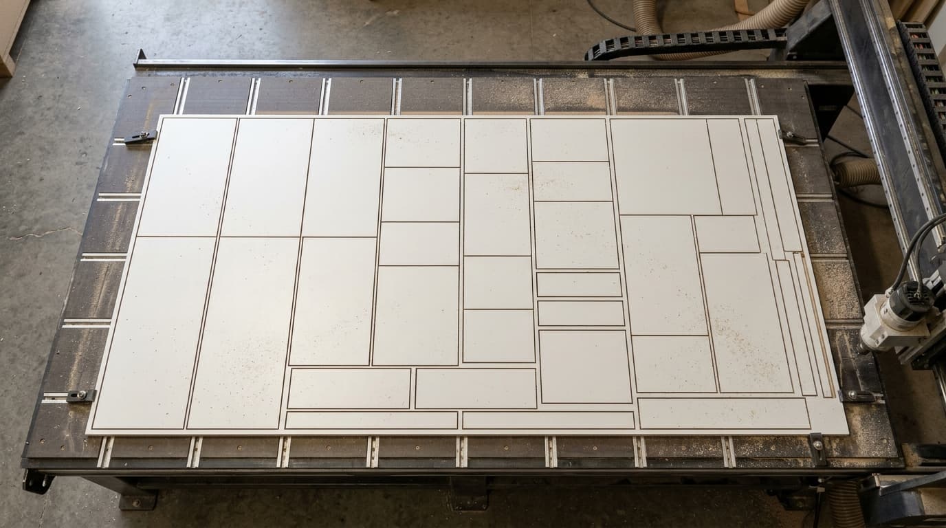
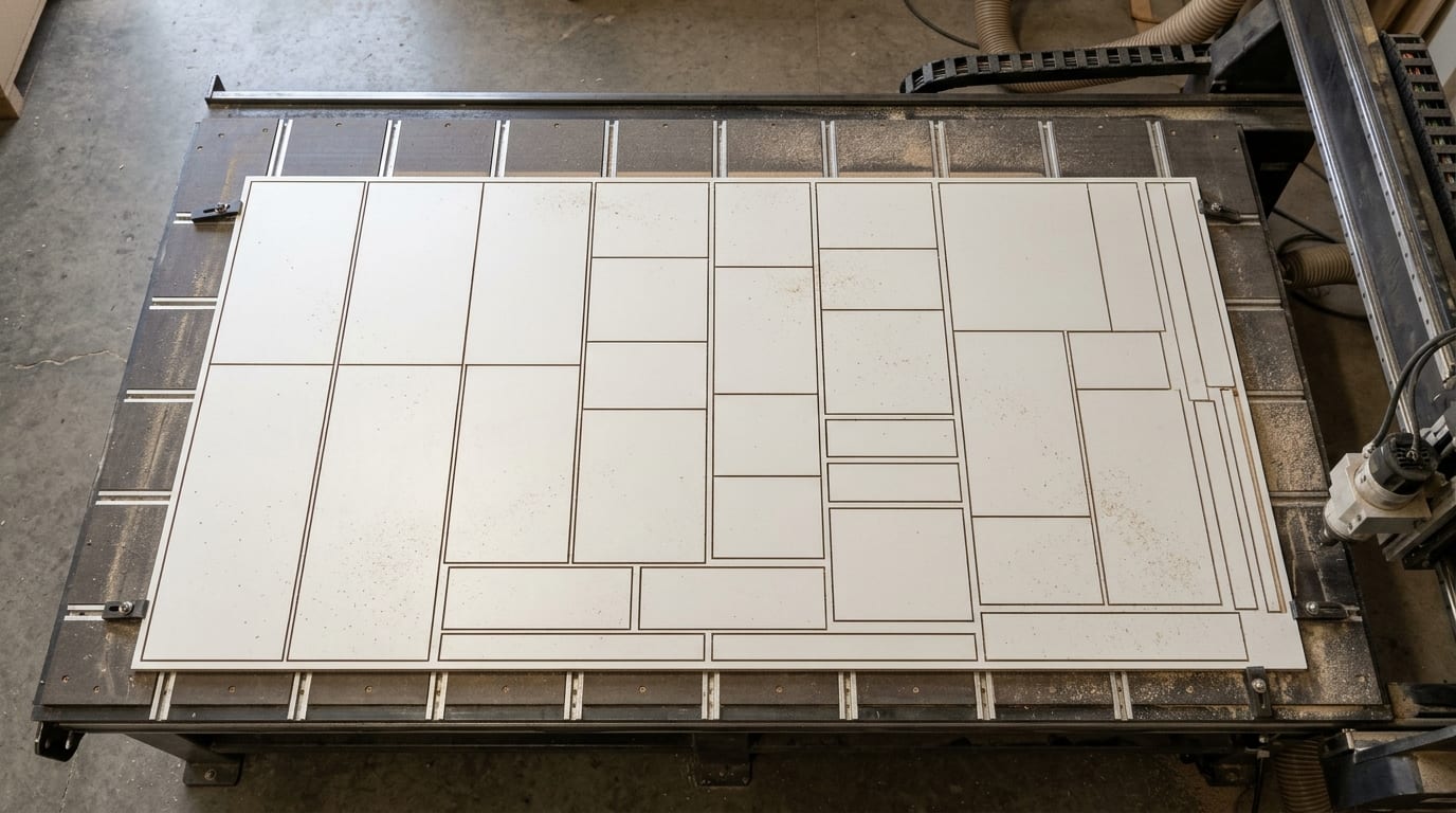
Cut white parts laid out on a sheet on the CNC table

Enter sizes into a table or load them from Excel and nest only those parts. Sizing parts go into the cut list, labels and CNC just like any other part.

Nesting

Export to CNC is available

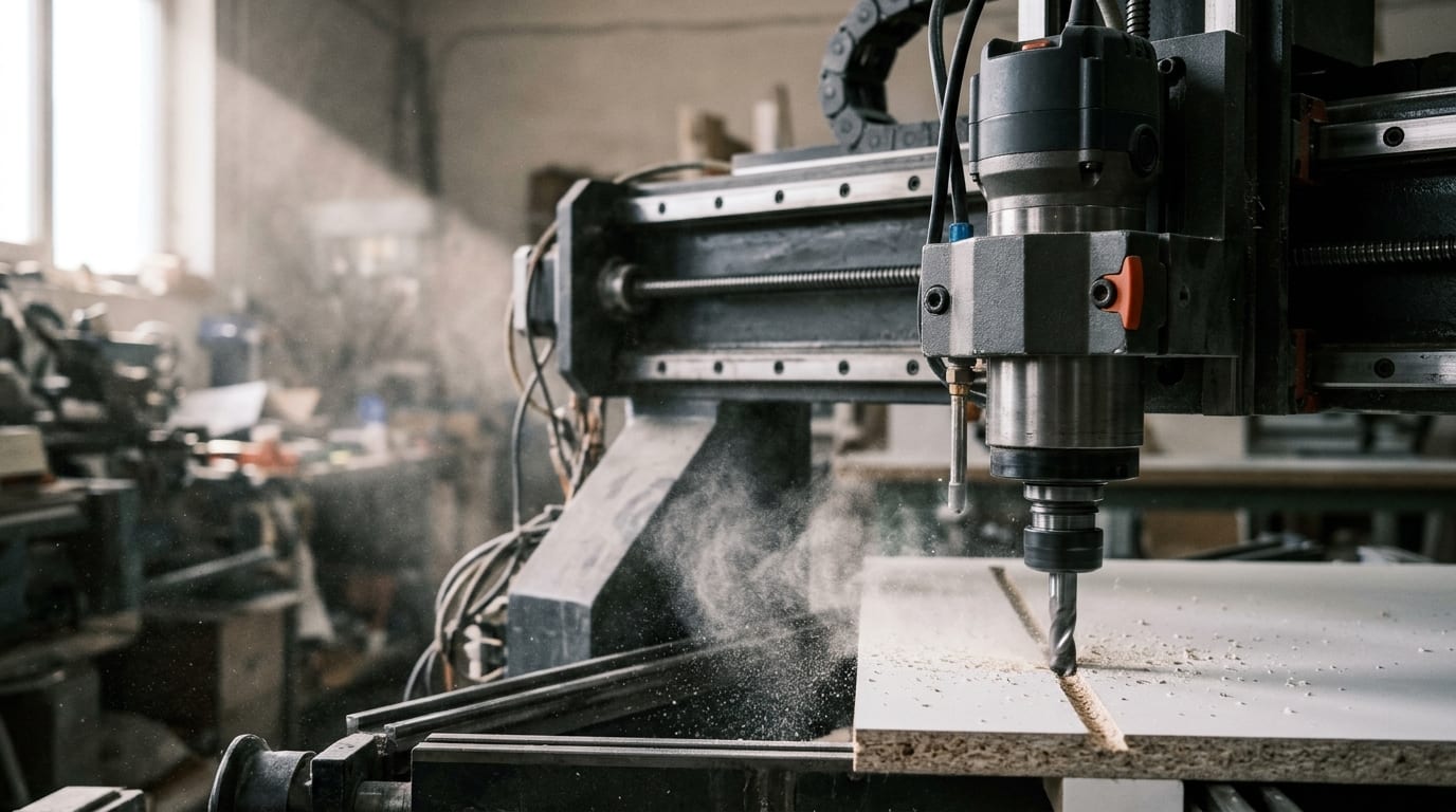
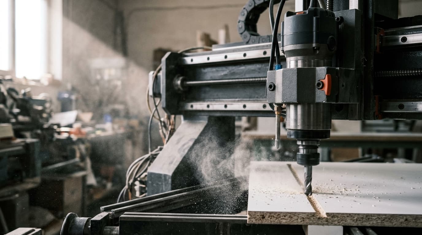
A CNC spindle cutting an MDF sheet

You get machine files straight from your drawing: G-code, DXF and CIX. G-code is written with your machine profile’s post settings.

G-code and CNC · Compare plans

  • Sizing area: enter sizes in a table or load them from Excel, then nest.
  • Export to CNC: G-code, DXF and CIX output.

  • Curved cabinets cannot be drawn yet.
  • Separate projects are not combined into one cutting plan.
Try it freeFor Windows · in both plans

From the release notes

The latest features and improvements.

  • Sizing area

    Enter sizes in a table or load them from Excel; nest only those parts.

    Read more
  • Export to CNC

    Machine files straight from the drawing.

    Read more
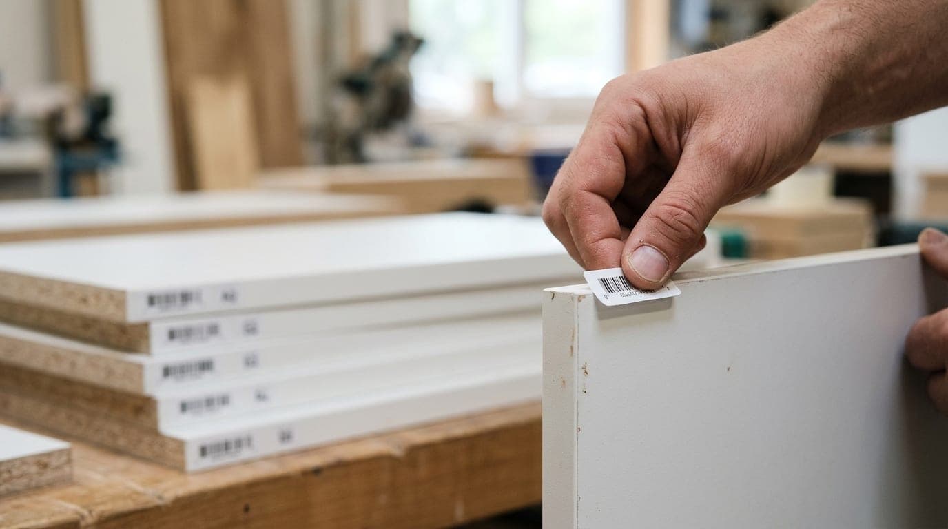
  • Part labels

    Barcoded labels right after CNC cutting.

    Read more

Cookie settings

Choose which cookies you allow. You can change your choice any time from the “Cookie settings” link at the bottom of the page.